Key Considerations in Designing and Building Semiconductor Burn-in Boards
Semiconductor burn-in is a critical process in ensuring the reliability and longevity of integrated circuits (ICs). It involves subjecting ICs to elevated temperatures and voltages for an extended period, accelerating potential failures and weeding out weak devices before they reach the end customer. Burn-in boards (BIBs) are the heart of this process, providing the electrical and thermal interface between the ICs under test (DUTs) and the burn-in system. Designing and building robust and reliable BIBs is a complex undertaking, requiring careful consideration of numerous factors, from electrical performance and thermal management to mechanical integrity and cost-effectiveness. This article delves into the key considerations for designing and building semiconductor burn-in boards, drawing upon industry best practices and resources like KES Systems, IEEE, and EDN.
-
Understanding the Burn-in Process and its Impact on BIB Design:

Before diving into the specifics of BIB design, it’s crucial to understand the burn-in process itself. Burn-in can be categorized into different types, such as static, dynamic, and high-temperature operating life (HTOL) burn-in. Each type imposes unique demands on the BIB.
-
Static Burn-in:
Applies constant voltage and temperature to the DUTs. This is the simplest form of burn-in and primarily stresses the devices electrically.
-
Dynamic Burn-in:
Applies clock signals and data patterns to the DUTs, simulating actual operating conditions. This type of burn-in stresses both the electrical and functional aspects of the devices.
-
HTOL Burn-in:
Combines high temperature with operating bias to accelerate the aging process and identify potential long-term reliability issues. This places the most stringent demands on the BIB, particularly in terms of thermal management.
The chosen burn-in type significantly influences the BIB design. For example, dynamic burn-in requires complex circuitry to generate and deliver the necessary test vectors, while HTOL burn-in necessitates robust thermal management solutions to maintain the desired temperature.
-
Key Design Considerations:
Designing a burn-in board involves a multifaceted approach, encompassing electrical, thermal, mechanical, and manufacturability aspects.
- Electrical Design:
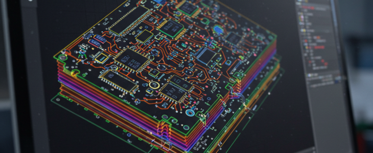
- Signal Integrity: Maintaining signal integrity is paramount, especially for high-speed digital ICs. This involves careful impedance control of transmission lines, minimizing signal reflections, and reducing crosstalk. Techniques like controlled impedance routing, proper termination, and the use of ground planes are essential. High-frequency characteristics of the chosen PCB laminate play a critical role here (discussed later).
- Power Distribution: The BIB must provide stable and clean power to all DUTs. This requires careful design of the power distribution network (PDN), including appropriate decoupling capacitors to filter noise and handle transient currents. Multiple voltage rails may be required, each with its own regulation and protection circuitry.
- DUT Interfacing: The interface between the DUT and the BIB is crucial. This typically involves using sockets or connectors that provide reliable electrical contact and can withstand the high temperatures of the burn-in environment. The choice of socket depends on the DUT package type, pin count, and pitch. Kelvin connections may be necessary for accurate current and voltage measurements.
- Test Vector Delivery (for Dynamic Burn-in): For dynamic burn-in, the BIB needs to receive and deliver test vectors to the DUTs. This may involve onboard pattern generators or interfaces to external test equipment. The design must ensure that the test vectors are delivered with the required timing and signal integrity.
- Protection Circuitry: Protecting the DUTs and the BIB itself is essential. This includes overvoltage protection, overcurrent protection, and electrostatic discharge (ESD) protection. Fuses, transient voltage suppressors (TVS diodes), and other protection devices are commonly used.
- Level Translation: If the DUTs operate at different voltage levels, level translation circuitry may be required to ensure compatibility with the burn-in system.
- Leakage Current Considerations: In high-temperature burn-in, leakage currents can become significant. The BIB design must minimize leakage paths and ensure accurate measurement of DUT leakage currents.
- Thermal Management:
- Heat Dissipation: Burn-in generates significant heat, especially with high-power devices. The BIB must effectively dissipate this heat to maintain the DUTs within their specified operating temperature range. This often involves using heat sinks, fans, or liquid cooling systems.
- Temperature Monitoring: Accurate temperature monitoring is essential to ensure that the burn-in process is performed at the correct temperature. Temperature sensors, such as thermocouples or thermistors, are placed near the DUTs to monitor their temperature.
- Thermal Modeling: Thermal simulations can be used to optimize the thermal design of the BIB and ensure adequate heat dissipation. This helps identify potential hotspots and optimize the placement of heat sinks and cooling devices.
- Controlled Thermal Environment: Maintaining a uniform temperature across the BIB is important. This can be achieved through proper airflow management and the use of thermal enclosures.
- Mechanical Design:
- Mechanical Stability: The BIB must be mechanically robust to withstand the stresses of the burn-in process, including repeated handling, temperature cycling, and vibration.
- DUT Mounting: The DUTs must be securely mounted on the BIB to ensure reliable electrical contact and thermal performance.
- Interface to Burn-in System: The BIB must interface seamlessly with the burn-in system, both electrically and mechanically.
- Size and Form Factor: The size and form factor of the BIB are often constrained by the burn-in system and the number of DUTs being tested.
- Manufacturability and Testability:
- Design for Manufacturing (DFM): The BIB should be designed for ease of manufacturing, including component placement, routing, and assembly.
- Design for Test (DFT): Test points should be included on the BIB to facilitate testing and troubleshooting.
- Component Selection: Components should be selected for their reliability, availability, and cost-effectiveness. High-temperature components are essential for HTOL burn-in.
III. Bill of Materials (BOM) Considerations:
The BOM for a burn-in board can be extensive and includes a wide variety of components, each with its own specific requirements.
- Sockets/Connectors: These are critical for interfacing with the DUTs and must be chosen based on the package type, pin count, pitch, and temperature requirements.
- Passive Components (Resistors, Capacitors, Inductors): These components must be rated for the appropriate voltage, current, and temperature. Low-ESR capacitors are often used in power distribution networks.
- Active Components (Transistors, Diodes, ICs): These components must also be rated for the burn-in environment.
- Thermal Management Components (Heat Sinks, Fans, Thermal Interface Materials): These components are essential for dissipating heat and maintaining the DUTs within their operating temperature range.
- PCB Laminate: The choice of PCB laminate is crucial, especially for high-temperature burn-in. This is discussed in detail in the next section.
- Hardware (Screws, Standoffs, etc.): These components must be compatible with the burn-in environment.
- PCB Laminate Selection and Types for High-Temperature Burn-in:
The PCB laminate is a critical component of the burn-in board, especially for high-temperature applications. The laminate must be able to withstand the high temperatures of the burn-in environment without degrading its electrical or mechanical properties.
- Key Properties: Several key properties should be considered when selecting a PCB laminate for burn-in applications:
- Glass Transition Temperature (Tg): The Tg is the temperature at which the laminate begins to soften and lose its mechanical properties. For high-temperature burn-in, a laminate with a high Tg is essential.
- Coefficient of Thermal Expansion (CTE): The CTE measures how much the laminate expands and contracts with changes in temperature. A low CTE is desirable to minimize stress on the DUTs and other components.
- Thermal Conductivity: High thermal conductivity is important for dissipating heat from the DUTs.
- Dielectric Properties: The dielectric constant and loss tangent of the laminate affect signal integrity, especially at high frequencies.
- Moisture Absorption: Low moisture absorption is important to maintain the electrical properties of the laminate.
- Types of Laminates for High-Temperature Burn-in:
- Polyimide: Polyimide laminates are known for their high Tg, excellent thermal stability, and good electrical properties. They are a popular choice for high-temperature burn-in applications.
- BT Epoxy: BT epoxy laminates offer a lower cost alternative to polyimide, while still providing good high-temperature performance.
- High-Tg FR-4: FR-4 is a widely used PCB laminate, and some high-Tg FR-4 materials are suitable for less demanding burn-in applications. However, they are generally not recommended for extreme high-temperature or long-duration burn-in.
- Specialty Laminates: For extremely demanding applications, specialty laminates with even higher Tg and improved thermal properties may be required.
- Considerations for High-Temperature Burn-in:
- Reliability: The laminate must be able to withstand repeated temperature cycling without degrading.
- Long-term Performance: The laminate must maintain its electrical and mechanical properties over the duration of the burn-in process.
- Cost: The cost of the laminate must be balanced against its performance requirements.
There are many considerations for designing a burn-in board. KES Systems, with it’s many decades of experience designing, building and using burn-in boards is ready to help you achieve the results you want. Please contact us for more information.