HAST BOARD DESIGN GUIDELINES
THB and HAST board DESIGN
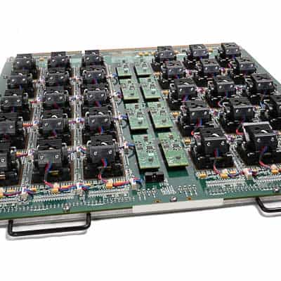
THB (Temperature Humidity Bias) and HAST (Highly-Accelerated Stress) Test boards are used to qualify device packages. These tests are used to evaluate the reliability of non-hermetic packaged devices in humid environments. There are important guidelines that must be followed when designing these types of Burn-In Boards to prevent premature failures in this harsh environment. Below is a list of critical HAST board design parameters:
1. Component Selection
2. Component Temperature Derating
3. Socket Selection
4. CAF /ECM Resistance
5. PCB Laminate Selection
1. Component Selection
The design team at KES has decades of experience selecting the right components for your board design. Using our HAST board design guidelines is an important first step toward success with your HAST testing. Key factors we consider when creating the bill of materials for the components in your design include power rating, component size, temperature derating, cost, safety margin, quality rating, life expectancy, availability, life cycle status, and alternate part options. All of these considerations are evaluated when selecting the components that will be used. Standard value components should be used whenever possible to improve part availability, reduce cost, and allow easy selection of alternate part sources. Below are standard capacitance and resistance values. The use of these commonly available part values reduces cost and the chances of running into part availability issues.
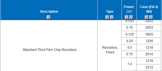
Standard SMT Resistor Sizes and Power Ratings
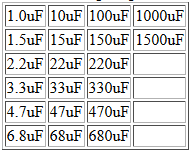
Standard Electrolytic and Tantalum Cap Values
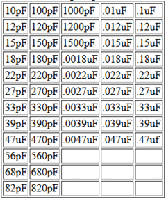
Standard Ceramic Chip Cap Values
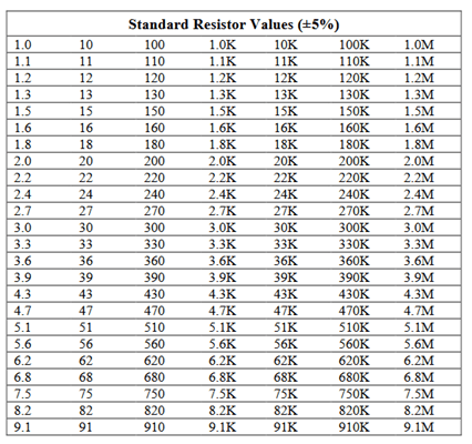
USE OF STANDARD VALUE COMPONENTS
Resistor tolerances are generally ±5%, ±2%, and ±1%. More accurate tolerances are available for some resistors, but these are not as widely available and costs are usually higher.
By using these standard part values, components from a variety of manufacturers can be chosen, making sourcing much easier and the cost of the components much less.

COMPONENT LEAD TIME CONSIDERATIONS
Non-standard and high-temperature components often have limited or no stock availability. KES has experts on staff to assist with creating a Bill of Materials for your project that contains parts that are available with short or no lead times.
2. COMPONENT TEMPERATURE DERATING
Temperature derating is a critical parameter to consider when selecting components including capacitors and resistors for use in board applications. For tantalum capacitors, voltage and capacitance derating at temperature is also important to consider. KES reviews the complete data sheet for every component that we select to ensure the part is robust enough for the intended application environment.
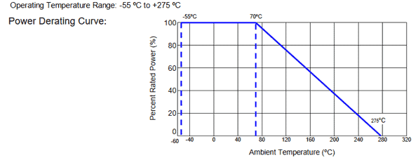
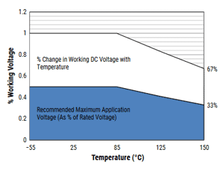
An example of a Power Derating Curve is shown in Figure 1 below. As you can see, for this particular resistor, the Rated Power at 150C is reduced to 60% of ambient temperature rated power so a 0.25 watt part would only safely dissipate 0.15 watts maximum at 150C. For tantalum capacitors, the maximum voltage also changes with temperature. For example, if the cap shown in Figure 2 below was rated at 100 volts, it can only safely be used at 33 volts maximum in a 150C environment.
!EMPTY!
3. SOCKET SELECTION
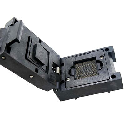
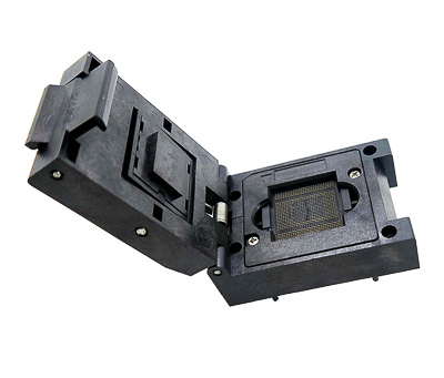
HAST and burn-In Board (BIB) test sockets allow for fast and reliable connection and change out of semiconductor devices to fulfill burn-in, humidity, failure analysis, and test requirements for Leaded, LGA and BGA packages. There are multiple manufacturers of board test sockets that offer both through-hole and compression mount type solutions. For HAST board applications, we recommend the use of compression mount sockets for higher voltage, high-density devices. Other factors to consider when selecting sockets include cost, availability, and reliability. KES has many years of experience in selecting and using all types and sockets and can assist on socket selection for your next project, and also offers custom sockets for multi-DUT and other applications.
4. CAF/ECM RESISTANCE
On HAST and THB type boards, Cathode Anode Filament (CAF) and Electrochemical Migration (ECM) is metal migration between isolated conductors on a completed printed circuit assembly may produce electrical shorts. KES has years of experience designing HAST boards to prevent these types of issues from occurring. The cleanliness of the board after assembly is also critical. Ions on printed circuit assembly surfaces can cause short circuits. In simple terms, shorts occur when the space between the conductors is bridged by dendrites formed by re-deposited metal ions. IPC describes this metal as a reverse plating of the conductors in the presence of ions, water, and electrical potential. In order to reduce the chance of CAF or ECM on THB or HAST boards, it is necessary to provide maximum air gaps between conductors especially supply voltages to ground to prevent CAF/ECM from occurring.
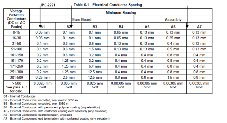
The air gap between conductors- Per the table below, the air gap between conductors is determined by the voltage across them per IPC-2221. Column B1 is the minimum spacing requirement for internal layer conductors and Column is the minimum spacing requirement for external conductors. These same minimum air gap requirements must be followed in the socket pad areas to avoid CAF/ECM issues. Through decades of experience and careful study, KES has developed a more advanced and comprehensive set of air gap and trace requirements to further minimize CAF and ECF issues in HAST and burn-in boards.
5. PCB LAMINATE SELECTION
PCB laminate selection is an important consideration for your HAST board. Many different laminate materials are available to support the requirements of your project. When selecting the laminate for your PCB board, many factors need to be taken into consideration including thickness, cost, lead time, copper weight, glass transition temperature (Tg), Decomposition temperature (Td), dielectric constant (Dk), dissipation factor (Df) and Coefficient of Thermal Expansion (CTE). Below are details about these parameters.
Tg = Glass Transition Temperature – This is the temperature at which a critical change in physical properties occurs. This is where the laminate transitions from a hard, glass-like material into a soft, rubbery material.
Td = Decomposition Temperature – This is the temperature where the laminate chemically decomposes.
While the effects of a Tg transformation self-reverse once the material is removed from its glass transition temperature, the effects of decomposition temperature on a substrate are permanent. Because of this, it is necessary to use a PCB material that can handle the temperature range of your working environment.
Dk = Dielectric Constant – This is the relative permittivity of an insulator material or its ability to store electrical energy in an electric field similar to capacitors. Laminates with a lower dielectric constant are better insulators.
Df = Dissipation factor – measures for the inefficiency of an insulating material showing the loss-rate of the energy of a mode of oscillation whether it be mechanical, electrical, or electromechanical.
CTE = Coefficient of Thermal Expansion – This is the expansion rate of a given laminate. When a substrate is exposed to temperatures that exceed its Tg, the material will also undergo a rise in CTE, which is measured in parts per million (ppm). A substrate layer will generally have a higher CTE than a copper layer. This difference is sometimes the source of interconnection problems when heat is applied so a low CTE (<70 ppm) is preferable to prevent connection issues.
We work with all the top PCB laminate manufacturers, such as Isola, Arlon, and Rogers to stay current with the latest technical developments in the industry.
Our HAST board design guidelines will help test and product engineers plan their next project. KES has experts on staff that can provide detailed information about laminate options and other recommendations for your project. Contact us to learn how we can help you. You can also email us at info@kessystems.com
